|
This circuit board can be used to replace all BCC1, BCC2, and BCC3 circuit boards. Replaces 65K29, 65K2901, LB-90089A ,48K98, 48K9801, 45K48, 45K4801,LB-89859, 78J61, 78J6001, LB-65126A.
BCC2−1 through BCC3−2 Blower Control
The BCC is a printed circuit board which controls the blower and monitors primary limit and gas valve operation. The control has a non−adjustable, factory preset on"fan timing. Fan off timings are adjustable. The board is divided into two sections, 120 and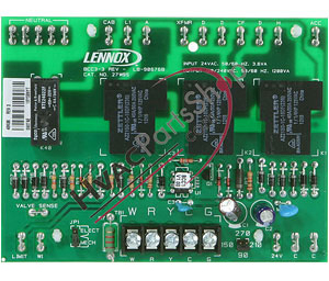 24VAC. Line voltage comes into the board on the120VAC side "CAB" and "XFMR " send 120VAC to the damper motor or combustion motor and transformer, respectively. The active cooling and heating blower speed terminals and three dummy "D" terminals are located on the 120VAC side of the BCC. Also located on the 120VAC side of the control are neutral terminals and a terminal for accessories such as an electronic air cleaner. The "HSI" terminal is not used. 24VAC comes from the transformer into terminal "24V" on the 24VAC side of the BCC. Thermostat connections and safety circuit terminals are also located on the 24VAC side of the control. Fan off timings may be adjusted by changing the position of a jumper across terminal pins. Thermostat terminal strips on early model BCC boards are removable. Late model boards have permanent thermostat strips. 24VAC. Line voltage comes into the board on the120VAC side "CAB" and "XFMR " send 120VAC to the damper motor or combustion motor and transformer, respectively. The active cooling and heating blower speed terminals and three dummy "D" terminals are located on the 120VAC side of the BCC. Also located on the 120VAC side of the control are neutral terminals and a terminal for accessories such as an electronic air cleaner. The "HSI" terminal is not used. 24VAC comes from the transformer into terminal "24V" on the 24VAC side of the BCC. Thermostat connections and safety circuit terminals are also located on the 24VAC side of the control. Fan off timings may be adjusted by changing the position of a jumper across terminal pins. Thermostat terminal strips on early model BCC boards are removable. Late model boards have permanent thermostat strips.
Blower Speed Taps
Blower speed tap changes are made on the BCC blower control board at the upper right corner. Unused speed taps must be secured to the dummy "D" terminals on the BCC. The active heating tap is connected to the "H" terminal and the active cooling tap is connected to the "A" terminal. To change a heating speed tap, turn off power, remove existing speed tap from the "H" terminal and place on "D" terminal. Next select new speed wire and place on "H" terminal of the blower control and restore power. Blower speed tap information can be found on the G20 unit wiring diagram.
|